Electronic Ignition - CB72, CB77, CP77, CL72, CL77 |
|
|
|
honda305 Forum | h305 Survey | h305 Marketplace | h305 Mailing List | h305 Auctions |
Installation Instructions
|
Vintage Racers | Motorcycles For Sale | Design | Featured Parts | NOS Parts | Classified Ads |
 |
Introduction:
The Model FS-01 electronic ignition is designed specifically for 1960s Honda models 250 Hawk (CB-72), 305 Superhawk (CB-77), 250 Scrambler (CL-72), and 305 Scrambler (CL-77), all with Type 1 engines. The Type 1 engines are differentiated by having their crankpins disposed at 180�, and have two carburetors and two sets of breaker points.
What should be in the kit:
The Model FS-01 kit includes the following components:
- Power Module
- Pickup Plate (with wire harness and connector)
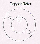
- Trigger Rotor
- Rotor Clamp (modified Oetiker-brand clamp)
- Self-adhesive Velcro pads (one "hooks," one "loops")
What else you will need:
In addition to the usual small hand tools required to get access to the engine’s breaker-points assembly and to remove the fuel tank, side panels, etc., installation will require the following tools and supplies:
- End-cutting pliers (or the Oetiker clamp installation tool, if you have access to one)
- Wire cutters/strippers
- Solderless crimp-type connectors, bullet connectors, or solder and shrink tubing
- Loctite medium-strength (blue) thread-locking compound or equivalent
Installation:
- Remove the side panels (for general access).
- Remove the seat.
- Disconnect the battery.
- Remove the fuel tank (you will need access to the ignition coils).
- Remove the alternator rotor cover (for setting the timing later).
- Remove the breaker points cover.
- Remove the breaker points and their backing plate as a complete assembly.
- Disconnect the breaker points from the ignition coils.
- Remove the condensers (you don’t need them with the solid-state ignition).
- Thoroughly clean and degrease the points cam with solvent. Commercial brake cleaner works well for this – wet a rag or paper towel with solvent and scrub the cam clean, including the end of the shaft.
- Using the original screws from the points backing plate, install the new Pickup Plate into the recess formerly occupied by the points backing plate. Don’t tighten the screws yet.
- Check to see that the Pickup Plate can be rotated in the housing with the screws loose. It’s a close fit and will sometimes bind if the housing has any damage or is a little small. If the plate won’t rotate easily with the screws loose, remove it now and take a couple of easy swipes with a file around its outside edge. Be careful not to slip off the edge and damage the components or leads. If there’s obvious damage to the alloy housing, clean it up with a small file or X-acto knife.
- Center the Pickup Plate’s mounting-screw slots on the screws and snug up finger-tight (you’ll have to loosen the screws again later to finalize the ignition timing).
- Carefully seat the grommet carrying the pickup leads into its recess in the points housing. Leave a little play in the wires so that the Pickup Plate can be turned later to finalize the timing.
- Route the wires from the Pickup Plate over the cylinder head similar to the original points leads.
- Find a place where you’d like to mount the Power Module. It’s best not to have it directly exposed to radiated engine heat, and mounting it in a zone with a little airflow when the bike’s moving is a good idea. It doesn’t take much airflow – don’t worry about a big breeze. The self-adhesive Velcro may be used to mount the Power Module, depending on where you’d like it.
- Look at the 10-pin connector at the end of the wire harness. On the connector’s rear surface (where the wires enter), there are molded-in numbers showing each wire’s position. Numbers 1 through 5 are in the first row (furthest away from the molded "latch"), and 6 through 10 are in the second row. The wires in each position are as follows (you only have to deal with the five heavy-gauge wires shown in boldface type):
-
Position 1: Heavy-gauge red wire – goes to
switched +12 volts
- Position 2: Light-gauge red wire – goes to Pickup Plate
- Position 3: Light-gauge black wire – goes to Pickup Plate
- Position 4: Light-gauge black wire – goes to shield braid Position 5: Heavy-gauge green wire – goes to chassis ground
- Position 6: Heavy-gauge yellow wire – goes to left-cylinder coil
- Position 7: Heavy-gauge green wire – goes to chassis ground
- Position 8: Light-gauge yellow wire – goes to Pickup Plate
- Position 9: Light-gauge blue wire – goes to Pickup Plate Position 10:Heavy-gauge blue wire – goes to right-cylinder coil
- Wire routing – try to route the five heavy wires away from the bundle of light-gauge wires that goes to the Pickup Plate. Also, try to keep everything away from the high-voltage ignition wires to the spark plugs, especially if you’re using the original wire-core, non-suppression sparkplug wires and plug caps.
- The two heavy-gauge green wires (connector positions 5 and 7) go to a good chassis ground. All the usual notes apply regarding the ground being free of paint and being clean, bright metal.
- The heavy-gauge red wire (connector position 1) goes to a switched source of +12 volts from the battery. You can pick this up from the wire supplying +12 volts to the ignition coils.
- The heavy-gauge yellow wire (connector position 6) goes to the left-hand ignition coil (for the #1 cylinder, on the "shifter" side of the bike), in place of the wire that formerly went to one set of points.
- The heavy-gauge blue wire (connector position 10) goes to the right-hand ignition coil (for the #2 cylinder, on the "kickstart" side of the bike), in place of the wire that formerly went to the other set of points.
- Plug the connector into the Power Module. It’s keyed, so it only goes one way, but it will be obvious – the notch in the cover of the Power Module is to clear the latch of the connector. Make sure the connector is seated fully – the latch will engage when it’s fully home.
- Shake the tube of medium-strength (blue) Loctite or equivalent thread-locking compound for a minute to mix it up.
- Smear a couple of drops of thread-locking compound around the cylindrical part of the points cam (opposite the index mark stamped on the end of cam). Also smear a drop of thread-locking compound directly on the end of the points cam.
- Slide the Trigger Rotor onto the points cam until it bottoms on the end of the cam.
- Rotate the Trigger Rotor until the index mark stamped into the end of the points cam is centered in the "window" in the end of the rotor.
- Slip the Rotor Clamp over the Trigger Rotor. The ball attached to the clamp will engage the slot in the rotor – it will be obvious, and only goes one way.
- Carefully grab the "ear" at one end of the Rotor Clamp with the end-cutting pliers, and clamp down until the ear is deformed about 1/16" or so from its original profile. You’ve got to use end-cutters for this operation, because their jaws are perfectly parallel at all times as they close – diagonal cutters won’t work. Don’t pinch the ear off – we’re just trying to squeeze it down a little. (The special tool available for crimping Oetiker clamps looks just like end-cutting pliers, but has radiused, not sharpened jaws. Most folks don’t have the special tool lying around. The end-cutting pliers work just the same, and are available at any hardware store.)
- Grab the ear at the opposite end of the clamp, and deform it the same way you did the first ear in the previous step.
- Go back to the first ear and squeeze it a little more, then return to the second ear and give it another little squeeze. By now the clamp should be pushing the ball against the low spot of the points cam, forcing the cylindrical portion of the points cam against the ID of the Trigger Rotor.
- Check the alignment of the index mark on the end of the points cam to the window in the end of the Trigger Rotor. If the index mark is not perfectly centered in the window, grasp the rotor and turn it to realign the index mark. The Trigger Rotor should turn on the points cam, with some effort, until the Loctite sets up. Note that that if you try to reposition the Trigger Rotor clockwise on the points cam, you will have to overcome the initial turning of the points cam against the advancer springs first.
- Reconnect the battery.
- Disconnect the spark plug caps and install a spare set of plugs into the caps. Lay the metal base of the plugs down so they contact the cylinder head surface.
- Turn the ignition key to the "on" position.
- Kick the engine through a couple of revolutions while keeping an eye on the spark gaps in the two spare plugs. Each plug should spark in turn.
- Turn the ignition key to the "off" position.
- Disconnect the spare spark plugs and reinstall the plug caps on their respective engine spark plugs.
- Reinstall the fuel tank, open the petcock, and set the choke as required.
- Turn the ignition key to the "on" position.
- Start the engine using the kick starter. Avoid using the electric starter until after the final ignition timing is set.
- Warm up the engine a little bit, so that it will idle when you need it to.
- Connect a xenon-flash type timing light (the bright kind) to the right-hand (#2) cylinder’s plug wire, and connect the timing light to the battery.
- With the timing light operating, slowly rev the engine up to the full-advance RPM level (around 3,000 RPM or so). If the timing light "stops" the timing indicator between the two full-advance marks for the #2 cylinder, move the timing-light pickup to the left-hand (#1) cylinder’s plug wire and check its timing at full advance. It should be very close to that of the #2 cylinder’s full-advance timing position.
- If the timing is not correct, shut off the engine, loosen the screws holding the Pickup Plate and rotate the plate to correct the timing. For every 0.023" of rotation at the edge of the plate, the ignition timing will change about 2� at the crankshaft. Rotating the plate in the direction of Trigger Rotor rotation (clockwise) will retard the timing; rotating the plate counter-clockwise will advance the timing. After you’ve readjusted the timing, lightly tighten the Pickup Plate retaining screws.
- Restart the engine and recheck the timing. Repeat as required. If you run out of adjustment slot length in the Pickup Plate, grab the Trigger Rotor and slightly reposition it on the end of the points cam. (That’s why we installed the Trigger Rotor last – so the Loctite won’t be set up at this point.) If you ran out of Pickup Plate slot length while trying to retard the timing, reposition the Trigger Rotor slightly counterclockwise on the points cam. If you ran out of slot length while trying to advance the timing, reposition the Trigger Rotor slightly clockwise.
- Honda CB/CL-72/77 engines are sensitive to excessive timing advance, and can overheat and possibly seize if the timing is not correctly set – that’s why the timing is adjusted to be correct at the full-advance position. Once the full-advance timing is set, the timing at the normal idle speed should fall on or near the "F" mark on the alternator rotor. If it doesn’t, the problem is with the centrifugal advance mechanism.
- When the timing is correctly set, turn off the ignition key, close the petcock, and reinstall the alternator rotor cover, the seat, and any other covers or bodywork.
Other details and notes:
- IMPORTANT: NEVER TURN ON THE IGNITION AND LEAVE IT ON FOR MORE THAN 1 MINUTE WITHOUT STARTING THE ENGINE! WHEN THE ENGINE IS NOT RUNNING AND THE KEY IS IN THE "ON" POSITION, THE POWER MODULE IS OPERATING "FULL-ON," AND CAN OVERHEAT VERY QUICKLY.
- The Model FS-01 ignition will work fine with stock ignition coils (about 4.5 ohm primary resistance). For those wishing to use higher-performance coils, a coil with a primary resistance down to about 3.0 ohms is permissible. If you use performance coils, give some thought to mounting the Power Module where it will receive a little more airflow and be away from radiated engine heat, as the module itself will run warmer with low-resistance coils.
- Coils intended for capacitive-discharge ignition (CDI) systems are generally less than 1 ohm primary resistance, and are incompatible with the Model FS-01 ignition system. The wrong ignition coils will cause very rapid, irreversible damage to the Power Module. Many inexpensive multimeters can’t measure accurately down to a few ohms, so be especially careful to know what coil resistance you’ve really got.
|
|
h305: Forum |
|||
| CB-77 | CYP-77 | Road Test | Riding Log | Literature | Zen | Marketplace | VJ Survey | Links | Home | |||